Motor Building Secrets

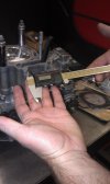
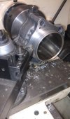
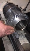
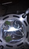
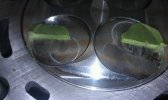
Now that the motor is on TDC we will measure the piston on the intake and exhaust sides. When measuring the intake side, push down on the exhaust side, to account for piston rock. We shoot for .040 total and that includes the .027 OEM or Cometic style MLS head gasket. So, we want the piston to be roughly .013 in the hole. I don't see any reason to run it any closer than .040, you decrease Piston to Valve clearance, increase the chance of the piston hitting the head, which will break the rod, and rod stretch.

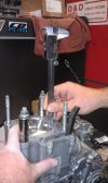
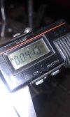
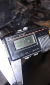
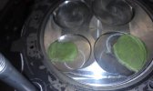
We use a set of digital calipers, Vernier or dial calipers, and a depth gauge will work fine as well.
 

Attachments

  • IMAG0239.jpg
    IMAG0239.jpg
    89.2 KB · Views: 115
  • IMAG0240.jpg
    IMAG0240.jpg
    97.2 KB · Views: 118
This illustrates an incorrect deck height at .041 on our calipers. We want .040 total so we know our current deck height is .041+.027 with our headgasket. With .068 we now know that .028 needs to come off the bottom of the cylinder for a correct deck height measurement. At this point remove the cylinder, and find a local machine shop that has means to cut the bottom of the cylinder. Do not try to cut the top of the cylinder, it will chip the Nikasil.

Chucked up in the lathe to cut and after cutting we smooth out any sharp edges with a piece of Scotchbrite.
 

Attachments

  • IMAG0241.jpg
    IMAG0241.jpg
    90.2 KB · Views: 82
  • IMAG0242.jpg
    IMAG0242.jpg
    91.7 KB · Views: 91
  • IMAG0243.jpg
    IMAG0243.jpg
    96.4 KB · Views: 91
  • IMAG0244.jpg
    IMAG0244.jpg
    93.8 KB · Views: 90
Re-install the cylinder in the same order as before, tighten down, and measure the deck height again. This time we come up with .013 on our calipers. We add the .027 for the headgasket and wind up right where we wanted at our .040.

The usual amount removed from the bottom of the cylinder is .010-.015 for most pistons depending on manufacturer, please remember I added base gaskets to get the illustrations.
 

Attachments

  • IMAG0246.jpg
    IMAG0246.jpg
    94.6 KB · Views: 34
Now that our deck height is set we can move onto clay checking the motor. This step is very important, none of us want to see the valves throw a party in the combustion chamber. We clay check with an old headgasket to get a more accurate reading, and new headgaskets should not be torqued down numerous times.

We have our Demon Pro head all shimmed up and ready to install on the motor with running lash .006/.009. Shimming a new head on the bench is always recommended if possible to avoid dropping shims down into the cam chain galley. For this head we will be running/clay checking with the Web 208/921, 36 Del West flat face Ti and Ferrea 31 stainless exhaust.
 

Attachments

  • IMG954119.jpg
    IMG954119.jpg
    89.9 KB · Views: 82
Place a small piece of modeling clay or Play Doh in the valve pockets of the piston. Overlap the clay over the edge of the valve relief to ensure that your piston will clear oversize valves if you are running them. Spray a small amount of WD-40 or oil on your finger and coat the top of the clay so that the valves leave their impression in the clay, but do not pick it up off the piston.
 

Attachments

  • IMAG0247.jpg
    IMAG0247.jpg
    96.4 KB · Views: 98
Install your head assembly with the motor on TDC and install the cam gear and cam chain with the lines level with the arrows on the cam tower. Install the cam gear bolts and the timing chain tensioner, extend the tensioner to ensure it doesn't skip timing when you roll it over. With your 8mm allen you used eariler, roll the motor over slowly 2-3 full rotations. Remove the head in the opposite order you installed it, and we are now ready to see what we have for Piston to Valve clearance.

When the head is removed you will be able to see that the valves have left their indentions in the modeling clay. Take note of the outer edge to make sure the valves are inside the valve pockets and not hitting. Next, cut the clay in half from intake to exhaust not from intake to intake. Dished valves must be checked against the lowest point at the rear of the valve relief. The center will give you a false reading. Take your calipers and measure the piece that is still on the piston and record. The absolute bare minimum is .050 on the intake and .070 on the exhaust. With this DASA LL piston our intake was .075 and the exhaust was at .096, adequate room on both sides, with slightly more to allow for even more to be cut off the head safely then we already cut off.

Wiseco and JE shelf pistons usually do not have the valve relief that CP shelf pistons do. Most CP shelf piston will allow .010-.015 off the cylinder and .015-.020 off the head with adequate piston to valve clearance.
 

Attachments

  • 100MEDIA36IMAG0294.jpg
    100MEDIA36IMAG0294.jpg
    89.8 KB · Views: 79
  • 100MEDIA36IMAG0295.jpg
    100MEDIA36IMAG0295.jpg
    79.3 KB · Views: 83
lol "secrets". great rightups. after what modifcations would you say you HAVE to check the the deck height? just before and after decking, and with long rod strokers?
 
Great stuff!

Couple of questions if you don't mind. Do you stick with .040 on all your engines or does it vary by manufacturer/engine size? How much of an effect does this have on compression ratio, is the whole point of this to increase compression? What is the stock deck height set at?
 
Hey morg, after removing .010-0.015 from the cylinder, is it enough to worrry about it affecting the cam timing, and to degree it, or is it minimal at that amount of material removed?
 
I wish Morgan would come on and finish this thread... this is one of the best threads on building I've ever come across. The secrets of doing a top end like a pro.
 
Back
Top